TR7 Modifications
 The following information was derived from a Drake company service bulletin for
the TR7 transmitter/receiver.
Due to the unavailability of RRM7 and RTM7 programming modules from the
manufacturer, the R. L. Drake Co. can no longer provide these items for the
TR7. Instead, the following modification is offered to replace the modules.
Part 1 of the modification enables the TR7 transmitter on all frequencies
between 1.5 at 30 MHz, while Part 2 allows reception in the 0-1.5 MHz range.
The two parts are not related, thus you may elect to perform only the part that
satisfies your requirement.
Caution: transmission outside the allocated Amateur band frequencies will
require a license, other than an amateur radio operator license, and may also
require an FCC certified transmitter. The TR7/TR7A is not an FCC certified
transmitter/receiver.


|
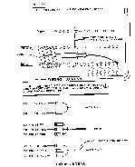
Click Here to view a larger size diagram of the modifications.
|
PART 1 All HF Frequency Coverage
- Unplug all interconnecting cables from the TR7.
- Place the radio upside down, with the front panel facing you.
- Remove the bottom cover plate by removing ten screws and sliding the
plate to the rear.
- Refer to the diagram and identify connector pin
rows 1, 2 and 3 on the front right-hand corner of the parent board. Carefully
identify pin 11 in rows 2 and 3.
- Note that a foil trace connects pin 11 in rows 2 and 3. Using a sharp
knife, cut this trace in two. Use caution, and do not disturb any other
circuits.
- If part 2 will not be performed, reinstall the bottom cover plate and
reconnect all associated stationed equipment. Otherwise, procede to part 2.
- Your TR7 will now transmit on any frequencies between 1.5 and 30 MHz.
Be sure to observe all applicable rules and regulations regarding out of band
operation.

PART 2 Low Frequency Coverage
- If the TR7 has not been disconnected from all accessories and the
bottom cover removed, do so at this time. Turn the radio upside down with the
front panel facing you.
- Refer to the diagram and identify connector row
1 on the front right-hand corner of the parent board.
- Carefully label connector pins 1, 2, 3, 16, 17, 18, and 19 in row 1.
- Refer to be attached figures and prepare one group of two diodes and
two groups of three diodes. Use 1N4148 or equivalent diodes. Connect the
anodes of the diodes in each group together and attach a length of insulated
hook-up wire to the common anodes connection of each group.
- Carefully solder the diode groups in position per the attached figures.
Connect the cathodes of the diodes to the indicated foils and the free end of
each line of hook-up wire to the indicated connector pin. To avoid shorts, use
insulated sleeving as necessary, and dress the leads neatly. Position the TR7
wiring harness away from areas to be soldered to avoid damage to the harness.
- If your TR7 has an AUX7 card installed, be sure that positions 1, 2,
and 3 are blank.
- Check again for shorts, reinstall the bottom cover and reconnect the
TR7 to the other station components.
- Your TR7 will now receive 0-500KHz in AUX position 3, 500-1000KHz in
position 2 and 1000-1500KHz in position 1. It is normal for the SET BAND lamp
to glow in this mode. Use the 1.5 MHz bandswitch position for 0-1500KHz
reception.

If, after reviewing these instructions, you would prefer to have the
modifications performed by the R. L. Drake company for a nominal fee, Contact:
Service manager
R. L. Drake company
230 Industrial Drive
Franklin, Ohio 45005
Telephone (513) 746-6990

This information provided by:
Wayne Montague, VE3EFJ
4146 Marigold Crescent
Mississauga, Ont
Canada. L5L 1Y7
C/Serv (73057,3063)
I/net montaw@inforamp.net
Layout and Design Copyright © 1997 by Thom LaCosta
All Rights Reserved
 The following information was derived from a Drake company service bulletin for
the TR7 transmitter/receiver.
 The following information was derived from a Drake company service bulletin for
the TR7 transmitter/receiver.
