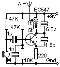

The circuit is very simple, and needs no explanation for construction although the kids needed some guidance when soldering. Surprisingly, I found the girls made a better job of soldering than the boys!
The coil is 1/4" (4mm) diameter and wound on a drill bit. A simple piece of insulated wire about 2 feet (60cm) was fine for the antenna, and is connected to a 1-turn tapping of the coil. Use tinned copper wire for the tuning coil and not the enamelled wire for kids to build. It is much easier for them to solder the antenna without "mashing-up" the coil, whilst trying to remove the enamel.
If you wish to use it from the headphone socket of an HF rig then delete the first 47K resistor and reverse the 1uf capacitor. The circuit shown is for an Electret condenser microphone. The transmitter may be received by any VHF FM radio, but the pocket radio I use about the house was free with WEETABIX box- tops a few years ago. It should have a range of at least 250 feet (75 meters) but increase the "220 ohm" emitter resistor to 1K to reduce the range (if you think that little Johnny could plant it in you and your wife's bedroom).
Incidentally, this little transmitter works well on 10 meters FM with a lower (and acceptable) deviation. The coil is 14 turns with a ferrite slug (tuning) and the tuning and feedback capacitors increased by a factor of 3. Take care with the positioning of the tuning coil, as this will alter the frequency. It should not be possible for a user to touch the coil. In the FM version this is of no consequence.
Have fun, de HARRY, Upplands Vasby, Sweden
I am very grateful to Harold, SM0VPO for allowing me to add his files to my web site. He can be contacted by email: harold.lythall@era.ericsson.se
Frank, G3YCC