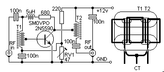

This is a rather unusual QRP Power Amplifier design, with a wide frequency
response; within a three dB's from 300KHz to 30MHz. Overall gain is in the
region of 16dB, and the final output power may be well over four watts.

The wide bandwidth is a result of the construction of the RF transformers,
T1 and T2. These are wound on 2-hole ferrite balun cores as commonly found
in the old fashioned valve TV sets (e.g. Phillips 4322-020-31520). Twist 2
lengths of 22 SWG enamelled wire together and wind as shown.   Connect the
end of the "A" winding to the start of the "B" winding.  Use this junction
as the centre-tap of the transformer.

This PA will deliver 4  watts continuously (with a suitable heatsink), and
may be loaded into a short-circuit or open circuit without causing damage.
This makes it almost the ideal PA for outdoor/field use.  The illustration
gives the full circuit diagram of the RFPA and the coil winding pattern. This PA
may be used for for SSB, as well as CW (and AM?).

Set RV1 to MINIMUM resistance and apply 12volt power with NO DRIVE. Adjust
RV1 for about 250mA DC total supply current.   This may be be reduced to a
much smaller current if lower output powers (reduced drive) is used.

Have fun, de HARRY, Upplands Vasby, Sweden
Frank, G3YCC